Part Builder Pin-Extract Information Sources
PartBuilders Pin-Extract Function, is focused on obtaining Pin Information for an electronic component, quickly, efficiently and most important, accurately . At a minimum, the tool needs to gather the pin name, pin number, and pin type (input, output, inout, power) for every pin of the component. Other information like the electrical io standard used for the pin or an alternate name for the pin can also be stored.
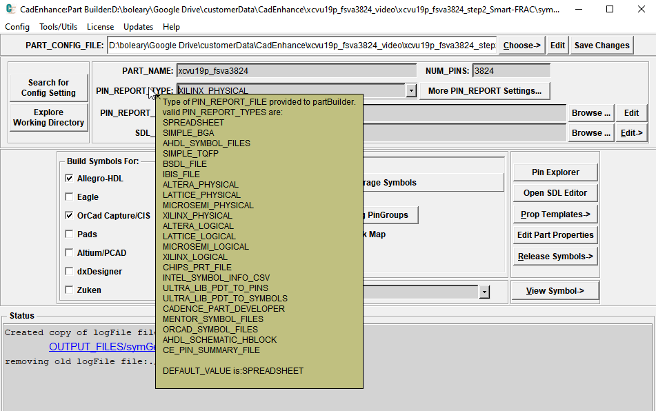
With the large variety of electronic components and manufacturers in today's market, it stands to reason that there are many different formats and or file types that can be used to provide the information. CadEnhance provides support for many industry standard and vendor file types that provide this kind of pin information, and can easily be extended to work with new formats as they are developed.
In some cases the only available pin information is a table or list in a datasheet. In these cases, the input must be compiled manually by the user and CadEnhance provides several efficient methods for inputting this information using text files built in a text editor or a SpreadSheet.
For low pin count parts it is a relatively simple task to enter the information, but as pin counts grow into the hundreds and thousands, processing the pin information from some available standard files becomes imperative
- Manual Sources
- SPREADSHEET (released after v18.11.1) This is very similar to GENERIC_CSV type, but PartBuilder can directly read the .xlsx file instead of forcing the user to save the spreadsheet tabs as .csv files
- SIMPLE_BGA
- SIMPLE_TQFP
- PIN_NUM_TYPE_FILE This is a special form of SPREADSHEET
- PINOUT_TEMPLATE (Old format where Pins and Symbol Layout were specified in one file not in much use these days)
- Industry Standard Sources
- BSDL File
- IBIS File
- Vendor Specific Formats
- Xilinx Package file used in XILINX_PHYSICAL and XILINX_LOGICAL flows
- Xilinx .pad file used in XILINX_LOGICAL flow
- Altera pins.txt file used in ALTERA_PHYSCIAL and ALTERA_LOGICAL flows
- Altera .Pin file used in ALTERA_LOGICAL flow
- Lattice .pad File used in LATTICE_LOGIGAL flow
- Cadence chips.prt File, used to redraw an existing symbol
- Intel SYMBOL INFO files. These are sometimes provided by Intel to describe the way they built the symbols for their device
- UltraLibrarian Files (available from many vendors like TI, Analog Devices)
- Existing EDA Symbols (These allow translation of an existing symbol from one EDA tool to another or provide a good way to get started with PartBuilder)
- AllegroHdl Symbols
- Mentor dxDesigner Symbols
- ORCAD Symbols
In all cases, the CadEnhance partBuilder tool reads pin information from the specially formatted files and stores them all in the same internal format to make processing the job of processing the pins consistent for all flows